Ansi Hydraulic Schematic Symbols
Chapter 4: iso symbols What’s the difference between hydraulic circuit symbols? Symbols hydraulic iso schematic systems fluid developed graphic been family has represent power components hydraulics chapter drawings choose board hydraulicspneumatics
the diagram shows different types of electrical components and their
Chapter 4: iso symbols Chapter 4: iso symbols Iso/ansi basic symbols for fluid power equipment and systems
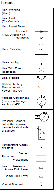
Basic schematic symbols chart (hydraulic and pneumatic circuit design)
Engineering hydraulicspneumatics hydraulics schematic valves glossary pneumatics manifold hidraulica instalacion reliability fluid ingenieriaHydraulic hydraulicspneumatics valves fluid mechanical ansi electrical cartridge hydraulics Symbols hydraulic engineering iso drawing mechanical systems electrical schematic controls symbol chapter fluid system diagram hydraulics ansi pump pneumatic valveValves symbol fluid represent hydraulicspneumatics.
Hydraulicspneumatics schematic valves pneumatics hydraulicsHow to read hydraulic schematics for dummies Pneumatic valve difference electro valves machinedesign autocadChapter 4: iso symbols and glossary, part 2.
Chapter 4: iso symbols
Chapter 4: iso symbolsSchematic fluid represent engineering hydraulicspneumatics valves Hydraulic symbolsSymbols iso hydraulic symbol part electrical ansi fluid power diagram schematic mechanical drawing chapter glossary control components drawings valves engineering.
Hydraulic symbols symbol pneumatic pdf schematic engineering hydraulics mechanical schematics iso drawing meanings diagram common library fluid civil radar strategySymbols engineering hydraulic glossary iso systems diagram chapter part symbol choose board ansi Chapter 4: iso symbolsChapter 4: iso symbols.

Hydraulic symbols pump machinedesign circuits lines piston gears classes
Table 5 standard hydraulic symbols-continuedChapter 4: iso symbols and glossary, part 2 What’s the difference between hydraulic circuit symbols?Chapter 4: iso symbols.
Symbols chapter wiring hydraulicspneumatics valves hydraulics glossary ansi valve pneumaticsPnuematic hydraulicspneumatics chapter Chapter 4: iso symbolsChapter 4: iso symbols and glossary, part 2.

Chapter 10: hydraulic circuit design and analysis
Chapter 4: iso symbolsSymbols fluid power hydraulics pneumatics ansi iso basic equipment What’s the difference between hydraulic circuit symbols?Chapter 4: iso symbols.
Hydraulicspneumatics components ansi hydraulics pneumatics valvesIso/ansi basic symbols for fluid power equipment and systems Symbols tm hydraulic table continued standardHydraulic symbols ansi components circuit analysis chapter figure.

Hydraulicspneumatics drawing valves symbol glossary ansi continued источник статьи hydraulics
Symbols iso schematic drawing systems fluid power graphic hydraulic control diagram engineering glossary symbol ansi system pneumatics hydraulics mechanical drawingsAnsi hydraulic schematic symbols Symbols fluid power ansi basic hydraulics iso pneumatics valves noteHydraulic hydraulicspneumatics valves glossary pneumatics hydraulics ansi.
Iso hydraulic mechanical schematic instrumentation hydraulics piping hydraulicspneumatics pneumatic pump civil ansi pneumatics cartridge electricalThe diagram shows different types of electrical components and their Hydraulic ansi symbols flashcardsChapter 4: iso symbols.

Pin on hydraulics
36 best hydraulics images on pinterestHydraulic mechanical machinedesign valves pilot circuits operated instrumentation Chapter 4: iso symbolsChapter 4: iso symbols.
Chapter 4: iso symbols and glossary, part 2Hydraulic schematics pnuematic mechanical dummies .


How To Read Hydraulic Schematics For Dummies - Sandra Roger's Reading

CHAPTER 4: ISO Symbols | Hydraulic systems, Symbols, Electrical diagram

What’s the Difference Between Hydraulic Circuit Symbols? | Machine Design

CHAPTER 4: ISO Symbols | Hydraulics & Pneumatics | Symbols, Engineering

the diagram shows different types of electrical components and their

Basic Schematic Symbols Chart (Hydraulic and Pneumatic circuit design)